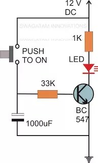
Capacitor Timer Circuit
Here 555 timer is operated in monostable mode. Use at least minimum 2200uf 25v capacitor and connect a 56k ohm resistor to parallel of this capacitor for discharging fastly.

Efa Ic 555 Mansteri University

Waveform Shaping The 555 Timer

Time Delay Relay Circuit Diagram Wiring Schematic Diagram
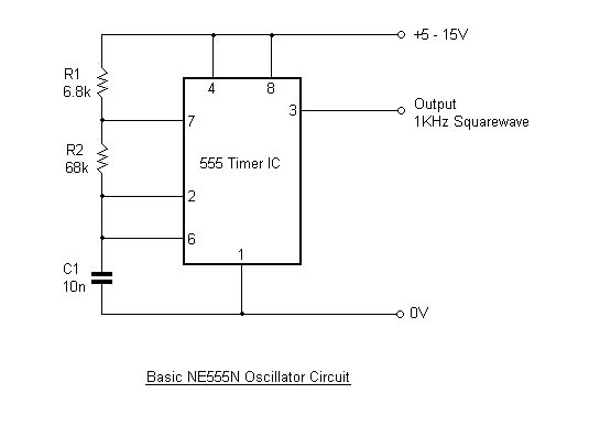
The 555 circuit is a conventional astable multivibrator that puts out a square wave with a frequency of a few hundred kilohertz.

Capacitor timer circuit. The 100k pot allows frequency tuning to get the lowest possible voltage across the cap. A capacitor which is the crucial part of the circuit gets the specific position in the circuit we can see that its been placed at the other end of the base resistor and not directly to the base of the transistor. Collect the below mentioned components to design the timer circuit of different time duration.
When the trigger input is applied555 timer produces a pulse. On depressing the button momentarily. A switch or link on the breadboard is closed to start the timer causing the led to switch off for a time period.
Multiply that value by 5 and you have a capacitor charge time of 10 seconds. Since were using a 100mf capacitor and there is a resistance of 20k in the circuit the time constant is 0001f x 20000r 2 seconds. When a voltage source is applied to an rc circuit the capacitor c charges up through the resistance r all electrical or electronic circuits or systems suffer from some form of time delay between its input and output when a signal or voltage either continuous dc or alternating ac is firstly applied to it.
When the circuit is powered by a 9v battery the led switches on. This pulse width depends on r and c values. The above proposed circuit is a 1 10 minute timerwhen pot is minimum it gives 1 minute delaywhere maximum value of pot can produce 10 minutes.
A push button is used to initiate the circuit. At this frequency almost all capacitors act like a short. The transient response time or the time the capacitor takes to charge fully is equal to 5 times this value.
In this circuit no any timer ic is used so the construction of this project is easy. After the time period is over the led will switch on again.

Off Delay Timer Circuit Simple Time Delay Circuit 555 Timer

Solved Design An Asynchronous Pacemaker Timing Circuit Us

Time Delay Circuit With Capacitors Transistors Resistors

What Is The Job Of The Capacitor In A 555 Circuit

Making A Digital Capacitance Meter Using Microcontroller

Blinking Led Circuit With Schematics And Explanation

What Is The Timer Circuit That Can Be Used To Delay Off For

How To Build A Simple Alarm System

How Does The 555 Timer Ic Circuit Work Electrical

555 Variable Frequency Square Wave Generator Electronic

555 Timer Oscillator Electronic Circuits And Diagrams

Single Mosfet Timer Circuit Homemade Circuit Projects
Comments
Post a Comment